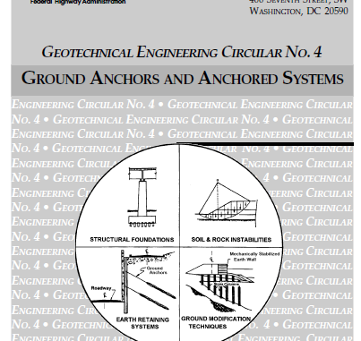
GROUND ANCHORS AND ANCHORED SYSTEMS (ZEMİN ANKRAJLARI VE ANKRAJLI SİSTEMLER)
Table of Contents – İçerik
Chapter 1 – INTRODUCTION
1.1 Purpose
1.2 Anchored System Service Life
1.3 Background
Chapter 2 – GROUND ANCHORS AND ANCHORED SYSTEMS
2.1 INTRODUCTION
2.2 GROUND ANCHORS
2.2.1 General
2.2.2 Types of Ground Anchors
2.2.2.1 General
2.2.2.2 Straight Shaft Gravity-Grouted Ground Anchors
2.2.2.3 Straight Shaft Pressure-Grouted Ground Anchors
2.2.2.4 Post-Grouted Ground Anchors
2.2.2.5 Underreamed Anchors
2.2.3 Tendon Materials
2.2.3.1 Steel Bar and Strand Tendons
2.2.3.2 Spacers and Centralizers
2.2.3.3 Epoxy-Coated Bar and Epoxy-Coated Filled Strand
2.2.3.4 Other Anchor Types and Tendon Materials
2.2.4 Cement Grout
2.3 ANCHORED WALLS
2.3.1 General
2.3.2 Soldier Beam and Lagging Wall
2.3.2.1 General
2.3.2.2 Soldier Beam
2.3.2.3 Lagging
2.3.2.4 Construction Sequence
2.3.3 Continous Walls
2.4 APPLICATIONS OF GROUND ANCHORS
2.4.1 Highway Retaining Walls
2.4.2 Slope and Landslide Stabilization
2.4.3 Tiedown Structures
Chapter 3 – SITE INVESTIGATION AND TESTING
3.1 INTRODUCTION
3.2 FIELD RECONNAISSACE
3.3 SUBSURFACE INVESTIGATION
3.3.1 General
3.3.2 Soil and Rock Stratigraphy
3.3.3 Groundwater
3.4 LABORATORY SOIL AND ROCK TESTING
3.4.1 General
3.4.2 Classification and Index Properties
3.4.3 Shear Strength
3.4.4 Consolidation
3.4.5 Electrochemical Criteria
3.5 IN SITU SOIL AND ROCK TESTING
Chapter 4 – BASIC PRINCIPLES OF ANCHORED SYSTEM DESIGN
4.1 GENERAL DESIGN CONCEPTS FOR ANCHORED WALLS
4.2 FAILURE MECHANISM OF ANCHORED SYSTEMS
4.2.1 General
4.2.2 Failure Mechanisms of the Ground Anchor
4.2.3 Failure of Soldier Beams
4.2.4 Failure Lagging
4.3 SELECTION OF SOIL SHEAR STRENGTH PARAMETERS FOR DESIGN
4.3.1 General
4.3.2 Drained Shear Strength of Granula Soils
4.3.3 Undrained Shear Strength of Normally Consolidated Clay
4.3.4 Undrained Shear Strength of Overconsolidated Clay
4.3.5 Drained Shear Strength of Overconsolidated Clay
4.4 EARTH PRESSURES
4.4.1 General
4.4.2 Active and Passive Pressure
4.4.3 Earth Pressure at Rest
4.4.4 Influence of Movement on Earth Pressure
Chapter 5 – DESIGN OF ANCHORED SYSTEMS
5.1 INTRODUCTION
5.2 EVALUATION OF EARTH PRESSURES FOR WALL DESIGN
5.2.1 Introduction
5.2.2 Background
5.2.3 Terzaghi and Peck Apparent Earth Pressure Diagrams
5.2.4 Recommended Apparent Earth Pressure Diagram for Sands
5.2.5 Recommended Apparent Earth Pressure Diagram for Soft to Hard Fissured Clays
5.2.6 Remommended Apparent Earth Pressure Diagram for Soft to Medium Clays
5.2.7 Loading Diagrams for Stratified Soil Profiles
5.2.8 Sliding Wedge Anaysis Method
5.2.9 Water Pressures
5.2.10 Earth Pressures Due to Surface Loads
5.2.10.1 Uniform Surcharge Loads
5.2.10.2 Point Loads
5.3 GROUND ANCHOR DESIGN
5.3.1 Introduction
5.3.2 Location of Critical Potential Failure Surface
5.3.3 Calculation of Ground Anchor Loads from Apparent Earth Pressure Diagrams
5.3.4 Design of Unbonded Lenght
5.3.5 Compression Anchors
5.3.6 Design of the Anchor Bond Lenght
5.3.7 Spacing Requirements for Ground Anchors
5.3.8 Selection of Prestressing Steel Element
5.4 WALL DESIGN ON LATERAL PRESSURES
5.4.1 Design of Soldier Beams and Sheet-Piles
5.4.2 Design of Lagging for Tempraroy Support
5.4.3 Design of Wales and Permanent Facing
5.5 LATERAL CAPACITY OF EMBEDDED PORTION OF WALL
5.5.1 General
5.5.2 Evaluation of Ultimate Passive Resistance
5.5.2.1 Soldier Beam and Lagging Walls
5.5.2.2 Continuous Walls
5.5.3 Depth of Penetration Below Excavation
5.5.4 Comprasion of Wang-Reese and Brom Method for Compenent Soils
5.6 AXIAL CAPACITY OF WALLS
5.6.1 Introduction
5.6.2 Axial Load Evaluation
5.6.3 Axial Capacity Design of Driven Soldier Beams
5.6.3.1 General
5.6.3.2 Effective Stress Analysis for Driven Beams
5.6.3.3 Total Stress Analysis for Driven Beams in Clays
5.6.4 Axial Capacity Design of Drilled-in Soldier Beams
5.6.4.1 General
5.6.4.2 Cohesionless Soils
5.6.4.3 Cohesive Soils
5.6.4.4 Design Issues for Concrete Backfill of Predrilled Soldier Beam Holes
5.7 ANCHORED SLOPES AND LANDSLIDE STABILIZATION SYSTEMS
5.7.1 General
5.7.2 Design Concepts
5.7.3 Limit Equilibrium Calculations
5.7.3.1 Overall Approach
5.7.3.2 Method 1 Analysis
5.7.3.3 Method 2 Analysis
5.7.4 Modeling Lateral Wall Resistance in Limit Equilibrium Analyses
5.7.5 Comprasion of Methods to Evaluate Required Earht Load in Homogeneous Soils
5.8 GROUND MASS STABILITY
5.8.1 Introduction
5.8.2 Basal Stability
5.8.2.1 General
5.8.2.2 Evaluation of Bottom Heave Potential in Soft to Medium Clays
5.8.3 External Stability
5.8.3.1 Introduction
5.8.3.2 Evaluation of External Stability Using Limit Equilibrium
5.9 TIEDOWN DESIGN
5.9.1 Introduction
5.9.2 Uplift Capacity of Rock Tiedown Anchors
5.9.3 Uplift Capacity of Soil Tiedown Anchors
5.9.4 Design of Tiedown Anchors to Resist Hydrostatin Uplift
5.10 SEISMIC DESIGN
5.10.1 Introduction
5.10.2 Internal Stability Using Pseudo-Static Theory
5.10.2.1 Lateral Earth Pressure
5.10.2.2 Wall Design Considerations
5.10.2.3 Liquefaction
5.10.3 External Stability
5.10.3.1 Pseudo-Static Analysis
5.10.3.2 Seismic Deformation Analysis
5.11 OTHER DESIGN ISSUES
5.11.1 Wall and Ground Movement
5.11.2 Drainage Systems for Anchored Walls and Slopes
5.11.3 Wall System Appurtenances
5.11.4 Resisting the Upper Anchor Test Load
5.11.5 Anchored Walls for Fill Applications
Chapter 6 – CORROSION CONSIDERATIONS IN DESIGN
6.1 INTRODUCTION
6.2 CORROSION AND EFFECTS ON GROUND ANCHORS
6.2.1 Mechanism of Metallic Corrosion
6.2.2 Types of Corrosion for Prestressing Steel
6.3 CORROSION PROTECTION OF GROUND ANCHORS
6.3.1 Requirements of Corrosion Protection Systems
6.3.2 Design of Corrosion Protection Systems
6.3.2.1 General
6.3.2.2 Anchorage Protection
6.3.2.3 Unbonded Tendon Lenght Protection
6.3.2.4 Tendon Bond Length Protection
6.3.2.5 Protection Against Stray Currents
6.3.2.6 Corrosion Protection of Anchors for Structures Subject to Hydrostatic Uplift
6.4 SELECTION OF CORROSION PROTECTION LEVEL
6.4.1 General
6.4.2 Service Life of the Anchored Structure
6.4.3 Aggressivity of the Ground Environment
6.4.4 Consequences of Failure of the Anchored System
6.4.5 Cost for a Higher Level of Protection
6.5 CORROSION OF STRUCTURAL STEEL, CEMENT GROUT AND CONCRETE
6.5.1 Corrosion and Protection of Steel Soldier Beams and Sheet Piles
6.5.2 Degradation and Protection of Cement Grout and Concrete
Chapter 7 – LOAD TESTING AND TRANSFER OF LOAD TO THE ANCHORED SYSTEM
7.1 INTRODUCTION
7.2 CONCEPTS FOR MONITORING ANCHOR BOND ZONE CAPACITY
7.3 TESTING AND STRESSING EQUIPMENT
7.3.1 General
7.3.2 Equipment Used in Load Testing
7.3.2.1 Hydraulic Jack and Pump
7.3.2.2 Stressing Anchorage
7.3.2.3 Pressure Gauges and Load Cells
7.3.2.4 Dial Gauge to Measure Movement
7.3.2.5 Jack Chair
7.4 ANCHOR LOAD TEST
7.4.1 Introduction
7.4.2 Performance Tests
7.4.2.1 General
7.4.2.2 Procedures for Performance Test
7.4.2.3 Recording of Performance Test Data
7.4.2.4 Analysis of Performance Test Data
7.4.3 Proof Test
7.4.3.1 General
7.4.3.2 Proof Test Procedures and Recording and Analysis of Proof Test Data
7.4.4 Extended Creep Testing
7.4.4.1 General
7.4.4.2 Procedures for Extended Creep Test
7.4.4.3 Recording and Analysis of Extended Creep Test Data
7.4.5 Acceptance Criteria
7.4.5.1 General
7.4.5.2 Creep
7.4.5.3 Apparent Free Length
7.4.5.4 Ground Anchor Acceptance Decision Tree
7.4.5.5 Modification of Design or Installation Procedures
7.5 ANCHOR LOCK-OFF LOAD
7.6 LIFT-OFF TESTING
Chapter 8 – CONTRACTING APPROACHES
8.1 INTRODUCTION
8.2 METHOD CONTRACTING APPROACH
8.2.1 Introduction
8.2.2 Contract Documents for Method Approach
8.3 PERFORMANCE CONTRACTING APPROACH
8.3.1 Introduction
8.3.2 Implementing Performance Contracting Approach
8.3.2.1 Pre-bid Wall Design
8.3.2.2 Pre-bid Typical Section Design
8.3.2.3 Post-bid Wall Design
8.3.3 Contract Documents for Performance Approach
8.3.4 Review and Approval
8.4 CONTRACTOR DESIGN/BUILD APPROACH
8.5 RECOMMENDATIONS
Chapter 9 – CONSTRUCTION INSPECTION AND PERFORMANCE MONITORING
9.1 INTRODUCTION
9.2 INSPECTION ROLES UNDER CERTAIN CONTRACT APPROACHES
9.3 PRE-PROJECT PREPARATION
9.4 INSPECTION OF CONSTRUCTION MATERIALS
9.4.1 Introduction
9.4.2 Inspection of Wall Materials
9.4.3 Inspection of Ground Anchor Materials
9.4.4 Storage and Handling of Construction Materials
9.5 INSPECTION OF CONSTRUCTION ACTIVITIES
9.5.1 Surface-Water Control
9.5.2 Vertical Wall Element Installation
9.5.2.1 Drilled-in Soldier Beams
9.5.2.2 Driven Soldier Beams
9.5.2.3 Sheet-Piles
9.5.3 Excavation
9.5.4 Anchor Construction
9.5.4.1 Introduction
9.5.4.2 Anchor Hole Drilling
9.5.4.3 Tendon Insertion
9.5.4.4 Anchor Grouting
9.5.4.5 Anchorage Installation
9.5.5 Ancillary Wall Element Installation
9.5.5.1 Timber Lagging Installation
9.5.5.2 Wall Drainage System Installation
9.5.5.3 Horizontal Drains
9.5.5.4 Permanent Facing Installation
9.6 SHORT-TERM AND LONG-TERM MONITORING
9.6.1 Monitoring of Anchor Load Test
9.6.2 Short-Term Monitoring of Wall Pressure
9.6.3 Long-Term Monitoring
REFERENCES
BIBLIOGRAPHY
APPENDIX
APPENDIX A – Design Examples
APPENDIX B – Development of Wang – Reese Equations
APPENDIX C – Example Calculation of Bending Moment for Wall in Weak Cohesive Soil
APPENDIX D – Predesign Load Testing Procedures to Evaluate Ultimate Ground Anchor Load
APPENDIX E – Specification for Ground Anchors
APPENDIX F – Specification for Anchored Sheet-Pile or Soldier Beam and Lagging Wall

Bir yanıt bırakın